|
Raster,
No Sound and No Picture. When a complaint of this
type is encountered, the serviceman can frequently determine
whether or not the trouble is between the antenna and the
converter, or between the converter and the picture tube
simply by observing the pattern produced on the screen.
Set the contrast control to its maximum position, and adjust
the brightness control so that a reasonably bright raster
is obtained. Then notice whether "snow" appears
on the screen of the picture tube.
If "snow" is obtained on the face of the picture
tube, it usually indicates that all stages between the converter
and the picture tube are operating. This leaves only one
stage where the trouble is likely to occur, the rf amplifier.
A new tube should be tried in that circuit.
If "snow" is not obtained when the brightness
control and the contrast control are set for normal operation,
it indicates a defect in some stage between the mixer and
the sound take-off point.
In that classification we have only four stages: The oscillator,
the converter, and the input i-f amplifier in each of these
stages. If replacing the tubes in these stages does not
correct the complaint, further circuit tests will be necessary.
Sound, Raster, No Picture. This complaint
indicates that the defect is in one of the stages carrying
only the picture signal. As mentioned previously, the input
i-f amplifier, and all of the stages in the "front
end" also carry the sound signal and the trouble could
not be in any of these stages. This leaves the three video
i-f amplifiers, the video detector, and the video amplifier.
Check each tube used in these circuits by temporary substitution
of a new one; if that does not correct the complaint, circuit
tests will be necessary.
No Sound, No Raster. When neither sound nor
raster is obtained, it is logical to assume that a defect
exists in some circuit that is common to both sections.
By glancing at Fig. 1 you will notice that only one section
of the receiver satisfies that requirement-the low voltage
power supply. Therefore, you should try replacing the tube
or tubes in that stage, and check the individual circuit
components and dc voltage available, if necessary.
Occasionally a power supply defect will not remove the operating
potentials from the various stages, but will decrease them.
When that happens, the picture will become narrow, the sound
output will become weak, the picture will often go out of
focus, and the picture may-under certain conditions-decrease
in height. The usual reason for this complaint is a weak
rectifier, but defective filters can also cause the condition.
Sound,
Raster, Poor Focus. On those sets using electromagnetic
focus, the focus coil is usually connected in series with
the B+ line. Therefore, any change in the current drawn
by the receiver will change the current through the focus
coil and "de-focus" the picture.
Occasionally you will encounter a set that refuses to focus
properly even though the control is rotated to the end of
its range. This indicates that too much-or too little-current
is flowing through the focus coil, and if the filter condensers
were defective, the B+ voltage would decrease, and the current
flow would decrease. If one of the tubes that normally draws
a good good deal of current were weak, it could produce
this complaint. (In many of the older sets, a weak audio
output tube will decrease the current through the focus
coil sufficiently to produce this effect).
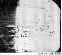
Fig.
5. Folding caused a defective damper. The exact
appearance of this complaint will vary depending upon
the connections between the damper and the horizontal
output stage.
|