|
Automatic
Volume Control Page 2
THE
DISTRIBUTION SYSTEM
The distribution system consists of the resistor capacity
network necessary to apply the d-c voltage developed across
resistor R1 to the grids of the various tubes being controlled.
There are four points to consider in checking the a-v-c
distribution system of a receiver. These are: (1) Voltage
distribution, (2) Filtering, (3) Time factor and (4) Cost.
We will consider these in the order named.
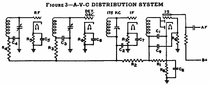
1- Voltage Distribution. Referring to Figure 3, we
will assume that the second detector is a Type 75 tube in
which the diode plates are paralleled in the conventional
half-wave circuit and used for developing both a-f and a-v-c
voltages. The triode section of the Type 75 is used as a
first audio stage, and to provide grid bias the cathode
is raised above ground potential by 1.5 volts with resistor
R8. This makes the cathode 1.5 volts positive with respect
to ground and, when no signal is being received, the control
grids of the first three tubes are biased 1.5 volts positive
also. To give the first three tubes a negative grid bias,
a cathode resistor is placed in each cathode circuit - resistor
R5, R6 and R7. The value of this resistor will, of course
depend upon the plate and screen grid currents of these
tubes. We can figure the voltage required, however, by allowing
1.5 volts to make up for the 1.5 volts positive potential
applied initially, then 1 volt for minimum grid bias and
2.0 volts to take care of any gas and/or emission present
which would buck out an equal amount of grid bias. This
gives us a required 4.5 volts that each that each cathode
should be raised above ground potential. For maximum sensitivity,
a lower bias is sometimes used and in some cases to eliminate
excess gain, a higher bias is applied.
Click
Image for a Larger View
2
- Filtering. In addition to the d-c a-v-c voltage
appearing across R1 (which is ordinarily about 1/2 megohm),
an a-f voltage is also present. This a-f voltage is coupled
to the grid of the Type 75 tube through condenser C9 and
is applied across resistor R9, (which is also ordinarily
about 1/2 megohm). To prevent this a-f voltage from feeding
back to the preceding grids and causing distortion, particularly
at low levels, resistor R2 is made large with respect to
R.9. If Resistor R2 is made at least 1 megohm, little or
no trouble will result from a-f or i-f coupling between
the second detector and the preceding tubes.
Resistors
R3 and R4 may be on the order of 100,000 ohms and in conjunction
with condensers C2, C3 and C4 will prevent r-f and i-f voltages
from feeding back to the preceding stage. Since condensers
C2, C3 and C4 complete the tuned circuits to ground, they
must not too small or some of the tuning range will be sacrificed.
These condensers may be from .01 to .05 mfd. Condensers
C5, C6 and C7 bypass r-f and i-f voltages across the cathode
resistors and are ordinarily about .1 mfd. Condenser C8
is by-passing a-f voltages and so must be about 2 to 5 mfd.
Back
  Next Next
<
1 2
3 >
|
|