Automatic
Volume Control
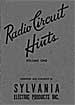
Radio Circuit Hints
Slyvania Electric Products, Inc
1943 |
|
CIRCUIT
NOTES
Very little data have been published regarding automatic
volume control circuits. Most of such data seem to try to
impress upon the reader how complicated automatic volume
control circuits are. In reality the fundamental principles
upon which an automatic volume control circuit functions
are the same as those upon which the action of a Type 80
rectifier circuit depends. In the radio field the Type 80
circuits are considered to be among the simplest.
To simplify the discussion of automatic volume control in
this article the a-v-c circuit has been stripped of all
of its accessories in order to study the generator system,
since that is the system which actually develops the bias.
After the generator system has been analyzed, a study will
be made of the distribution system, which is the network
of resistors and capacities by means of which the bias voltage
developed in the generator is applied to the grids of tile
tubes under control. It is felt that if these two separate
functions of ail a-v-c system are separated and studied
independently, that the a-v-c system will lose a great deal
of its seeming complexity.
GENERATOR
The Type 80 rectifier tube and the principle upon which
it operates is so well known that it furnishes an admirable
basis upon which to explain the action of the diode detector
used to generate a direct current for automatic volume control
purposes. A glance at figures 1 and 2 will show how nearly
identical both circuits are for full-wave
and half-wave operation. Tlie principle is the same in each
case. There are, however, three minor differences between
the Type 80 rectifier circuits and the diode detector circuits.
These are:
1
- The Type 80 rectifier operates from the power line which
furnishes a definite plate voltage at a frequency of 60
cycles. The diode detector operates from an i-f transformer
at a much higher frequency (which we will assume to be 175kc)
and the voltage on its plates varies as the signal being
received increases and decreases.
Naturally the rectified DC from the diode detector varies
in proportion to the i-f voltage impressed on its plates.
2 - The filter system employed to smooth out
the rectified direct current is much smaller and simpler
in the case of the diode detector because of the higher
frequency involved. Usually only one small fixed condenser
is necessary.
3 - The negative side of the load is grounded
in the Type 80 rectifier circuit and the positive side in
the diode detector circuit, since in one case we want a
positive voltage and in the other case a negative voltage.
By connecting the control grid return of a variable mu tube
to the negative side of the diode load, it will be apparent
that the bias on this grid will increase when a strong signal
impresses a higher i-f voltage on the diode plates. As the
grid bias increases on the control grid, the gain of the
tube decreases. This is the basis of the a-v-c action.
|